Content
1. Overview
2. Capturing User's Gesture
3. Robotic Hand Control
4. Haptic Feedback
5. Microcontroller
Methodology
1. Overview
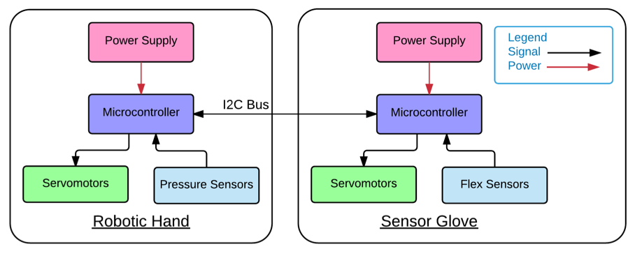
We can see that the Haphand system is divided into 2 main parts, the robotic hand and the sensor glove. They have similar structure, consist of a power supply, servo motors, sensors and a microcontroller that connects all the components. Both microcontrollers get signals from the sensors and provide signals to the servomotors. The robotic hand and sensor glove communicates using I2C Bus by the microcontrollers. This allows the microcontrollers to get signals and send signals to components that are not directly linked to them. The details will be explained later in Part 5 microcontrollers.

The above image shows the entire work flow of the Haphand system. After the Haphand is turned on, user’s gesture will be continuously monitored using flex sensors. If user moves his/her hand, system will check if user has touched anything with his/her finger using pressure sensors. If no, sensor gloves will be moved to maintain appropriate tension of the wire on user’s hand. Robotic hand will also be moved to mimic the user’s gesture. If user has touched something which means haptic feedback is required, sensor gloves will be moved to constraint user’s action and therefore provide a touching sensation to user.
2. Capturing User's Gesture
5 flex sensors are attached on each user’s finger. As mentioned before, flex sensors can measure its degree of bend by the vary in resistance across it. By measuring the degree of bend of each finger, the user’s gesture can be captured. If user’s gesture is continuously monitored, the user’s hand movement can be estimated.
However, the microcontroller cannot read the resistance of the flex sensors directly. Therefore, a voltage divider is required. Voltage divider is a passive linear circuit that produces an output voltage that is a fraction of input voltage. It is used to createreference voltages. Therefore, the change in resistance will be converted to change in voltage and can be read by the microcontroller as analog signals.
3. Robotic Hand Control
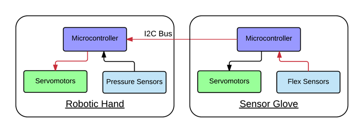
After capturing the user’s gesture using the flex sensor, the microcontroller of the sensor glove is programmed to analyze the analog data received then covert them to digital signals using Analog to Digital Conversion (ADC) on Arduino. This microcontroller will then transmit the digital signals to the microcontroller of robotic hand using I2C communication. The latter microcontroller will then transfer the received digital signals to analog signals and send to the servo motors to control the fingers. The signal path is shown as a red line in figure below.
The aforementioned analog signal is created by pulse width modulation (PWM). It is a technique used to encode a message into a pulsing signal. Different frequency of pulse represents different rotating angle. The servo will rotate to corresponding angle by receiving 500,000 to 2,500,000 ns duration of pulse.
There are 5 servo motors attached on the robotic hand. Each servo motor is link to the fingertips of the robotic hand with two wires. One is attached on the palm side and the other one is attached on the back side. Pulling the wire on the palm side will crook the finger while pulling the other wire which is on the back side will straighten the finger. The rotation direction of the servo motors will decide which wire is being pulled and therefore able to control the movement of each fingers and hence the gesture.
4. Haptic Feedback
5 pressure sensors are each attached on a fingertips of the robotic hand to detect the pressure applied on the robotic hand and send the signal back to the microcontroller of the robotic hand. Similar to flex sensors, the pressure is detected with the change of resistance across the pressure sensors which cannot be directly read by the controller. Therefore, a voltage divider is installed to transfer the change in resistance to change in voltage.
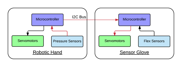
Detecting pressure applied on the pressure sensors represents the sensors are being pressed. The robotic hand is likely griping something and haptic feedback is required. After the microcontroller received the analog signal, it will analyze the signal and transfer to digital signal the transmit to the microcontroller of the sensor glove through I2C communication. The latter microcontroller will then transfer the digital signal back to analog signal using PWM and move the servomotors attached on the sensor glove. The signal path is shown as a red line in below figure.
5 servo motors are attached on the sensor glove. Each of them is linked to the user’s fingertips using 2 wire. When haptic feedback is required, both of the wire will be pulled to constraint the movement of the user and therefore create the sensation of feeling the object. The higher the pressure detected by the pressure sensor, the tighter the wire being pulled. User will experience a higher pulling force and stronger haptic feedback.
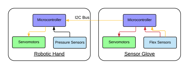
It is noteworthy that the servomotors attached on the sensor glove are not only affected by the pressure sensor on robotic hand. It will also move according to the signal received from flex sensor. This means when user moves his/her hand, the servos on both robotic hand and sensor glove side will be moved even when no pressure detected. Below figure shows both the signal paths when flex sensors are bent.
The reason is to maintain an appropriate tension of the wire linking the servos and user’s fingertips. If it is too tight, user’s movement will be constraint even when no pressure is detected. On the opposite side, if it is too loose, the servos will require a long time to tighten the wire again to provide the haptic feedback hence create an unresponsive user experience. As a result, the servos on the sensor glove side need to adopt with the user’s gesture, maintaining an appropriate tension without hindering the user’s fingers.
5. Microcontroller
In this FYP, 10 sensors and 10 servo motors are involved therefore 10 analog input pin and 10 digital I/O pin is required. However, the GSTduino only has 8 analog input pin which is not enough. As a result, 2 GSTduino boards have to be used and communication between microcontrollers is involved. The Inter-Integrated Circuit (I2C) Protocol is used for this purpose. It is a serial computer bus that allows multiple “slave” digital integrated circuits to communicate with usually one “master” chips. Only two signal wires are required, the SCL and SDA line. SCL is the clock line that used to synchronize all data transfers over the I2C bus while SDA is the data line. Master chips will be the device that drives the SCL clock line. When the master devices want to initiate the communication to the slave devices, it will begin by issuing a start sequence on the I2C bus then follow by the message and end with an ending sequence.
In this project, microcontroller of the sensor glove is the master device while microcontroller of the robotic hand is the slave service. Since the slave device cannot initiate a transfer over I2C bus, only master device can do so. Therefore, the microcontroller of sensor glove will constantly require the reading of the pressure sensor on robotic hand side.