The goal of this workshop is
to show the principle of lightning detection and
to introduce a simple circuit for detection of
strong electromagnetic signals or light flashes,
which are produced by electric sparks, lightning included.
The reader should note that while the principle applies to
lightning detection in general,
the circuit introduced is by no means
the only circuit for lightning detection.
When there is lightning,
strong but transient electromagnetic waves are produced.
On an oscilloscope,
the waveform looks like that shown in
Figure 1,
where the current induced by an electric arc generated by a manual electric arc lighter is shown.
Note the time scale on the horizontal axis of the graph.
The electromagnetic disturbance only last for a few milliseconds,
and so even if we can capture the disturbance,
we need to convert it into some longer-lasting signal so it can be seen by
an observer far from the detector.
Figure 1. Waveform of current induced by a free-air electric arc discharge
圖一.空氣中電弧放電的電感電流的波形
The reader is also reminded that real lightning
often consists of multiple electric arc discharges happening at different times during different stages of lightning.
Interested parties can refer to books such as [1] for more information.
So, a lightning detector needs to do two things:
Capture the electromagnetic disturbance
Convert the millisecond-long signal to a longer signal for display or recording
In the following sections,
we will introduce how these can be done in the lab setting.
Since the capturing circuit has more variations,
let's introduce the conversion circuit first.
From a flash to a second — the monostable 將一瞬變成一秒 — 單穩態電路
A circuit that converts a short pulse to a longer one is called a monostable circuit.
It is called "monostable" because it only has one stable state,
which, in our case, signals non-detection of the pulse.
A monostable circuit can be triggered into the other state by an input pulse.
In our case, it is the pulse from a detected electric arc.
There are many ways a monostable circuit can be constructed.
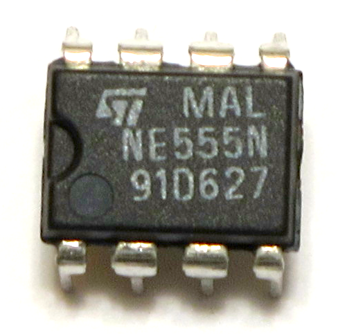
One relatively simple way is to use the timer integrated circuit (IC) NE555.
The IC is shown in Figure 2,
and the circuit is shown in Figure 3.
In this circuit,
a when the input to pin 2 of NE555 has a voltage
higher than 2/3 of the supply voltage Vs,
the output at pin 3 of NE555 will
go high (i.e., near to supply voltage) for a while,
determined by the resistor Rt and capacitor Ct.
The formula for the time that the output will go high is
t ≈ 1.1 Rt Ct.
With the monostable circuit in place,
what we need to do next is to generate the pulse that triggers it
when lightning is detected.
We can do it in a number of ways, some of which are listed as follows:
Use an inductor to pick up electromagnetic disturbances (Figure 4)
Construct a electronic inductor—capacitor resonator similar to that in AM radio, and tune it to a frequency of a few hundred kilohertz (Figure 5)
Construct a fast-reacting light sensor circuit that detects changes in light intensity (Figure 6)
We are going to give brief explanation of these circuits.
The idea for the design of this electromagnetic disturbance detector is very simple:
electromagnetic waves caused by lightning or electric arc
are able to induce currents in an inductor.
These current can be AC-coupled (alternating current-coupled),
to trigger the monostable.
In this circuit,
a coil is used as an inductor.
A capacitor is used to block direct currents,
and couple only the induced current to the monostable.
Note that since the induced current can flow in both ways
along the inductor,
the induced current spike have both a positive and a negative part.
Also, the current spike can be very large in amplitude.
To avoid damage to the monostable circuit,
sufficient protection should be in place.
For example,
a current limiter circuit can be used to limit the amplitude of the current spike.
An inductor stores energy as magnetic field,
and a capacitor stores energy as electric field.
Because there is a 180˚ phase difference
between these forms of energy storage,
coupling an inductor and a capacitor together
forms the basis of an electronic resonator.
Given
an inductor with inductance L and
a capacitor with capacitance C,
the resonant frequency f is 1/(2π√L̅C̅).
A lightning generates signal in many frequency bands,
but it would be convenient to tune the LC resonator
to the carrier frequency of an AM radio,
from about 400kHz to 1000kHz.
Since only a particular frequency is picked up by the LC resonator,
the signal would be relatively weak when compared with
the one picked up by just an inductor.
However,
since the spectral characteristics of lightning varies
across type and stage of lighting,
tuned resonators are often used in
advanced lightning detection and analysis systems.
To use this kind of resonator effectively,
some kind of amplification of the resonator output is often needed.
電感器利用磁場儲存能量,而電容器則利用電場來儲存能量。
因為它們儲存能量的方法有180˚的相位差,電感器耦合電容器可以造出一個諧振器。
若電感器的電感量為L,電容器的電容值為C,諧振器的諧振頻率 f 為 1/(2π√L̅C̅).
To detect sudden changes in light intensity,
we can use some fast-responding components
such as the light sensing elements used in a web camera,
or a photo diode.
Since a web camera is designed to interface with a computer
and the processing of its image has been covered in
a previous workshop,
here we focus on the use of a photo diode.
A photo diode,
like a normal diode,
allows current to flow in one direction only.
Yet,
different from a normal diode,
the amount of current flow is controlled by light intensity
that falls upon the photo diode.
More currents can flow when the incident light intensity is high,
Hence, a simple current-limiting circuit
is enough to capture light intensity.
To capture the change of light intensity,
a capacitor is used to block the direct current (DC)
part of the signal.
In general,
quick changes of light intensity would cause sudden change
of voltage on the diode end of the capacitor,
which generates a voltage spike on the load end.
This section guides you through the lab work for
the construction of a simple electric arc detector.
在本節,我們會帶大家製作一個簡單的電弧探測器。
Understanding the circuit diagram and components 認識電路圖和電子零件
Our first step is to construct the monostable circuit
whose schematic diagram is shown on
Figure 3.
Afterwards, a detector will be constructed to trigger the monostable circuit.
Before we start constructing the monostable circuit,
let's take some time to understand the diagram and
the components needed to construct the circuit.
All upward pointing arrows in the circuit diagram
connect to the positive side of the power supply,
and all symbols with three lines going downwards forming a triangle
are grounded to the negative side of the power supply.
The largest piece of component on the circuit diagram,
is a rectangle that corresponds to the IC NE555,
and the numbers are the pin numbers of the IC.
In the workshop,
the IC used is in Dual In-line Package (DIP),
and looks like that in Figure 2.
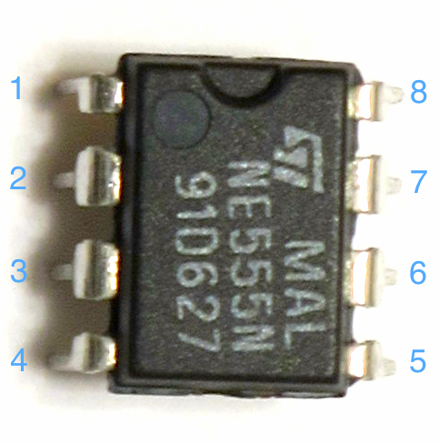
Note that there is a notch on the DIP IC.
If we put the notch at the top,
we can number the pins from 1 on
by counting counterclockwise from the top left hand corner,
as shown in
Figure 7.
In the circuit diagram,
the zig-zag symbol correspond to resistors.
Resistors limit current flow and its values are measures in ohms,
with the greek letter Ω as symbol.
The larger the value the resistor,
the smaller will be the current flow given the same voltage.
With a resistor value of R and a voltage of V,
the current I=V/R.
This can be remembered as V=IR.
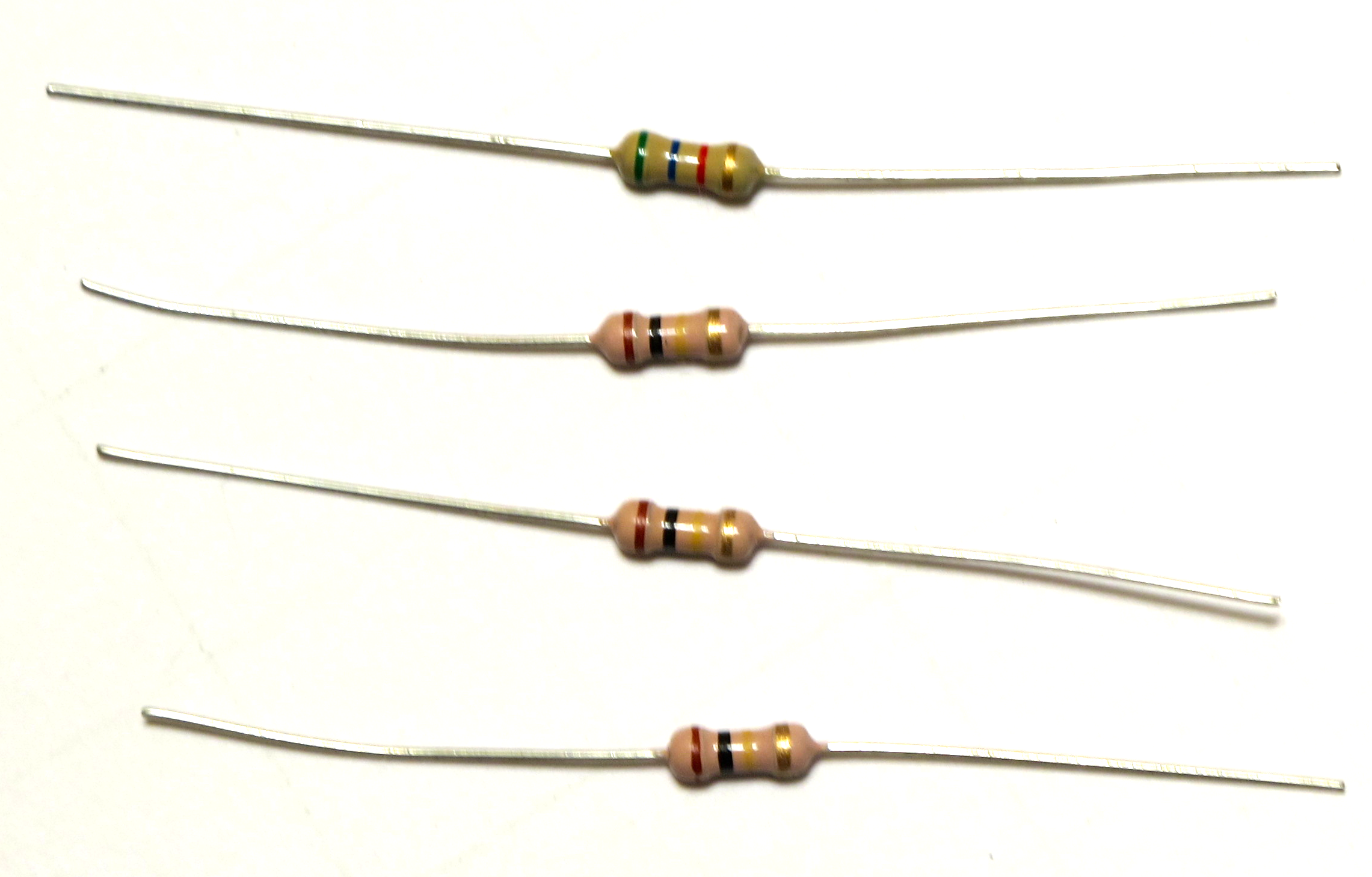
Resistors look like those in Figure 8,
and are nonpolar.
That is,
unlike batteries,
installing a resistor one way of another does not matter.
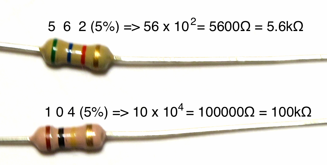
Resistor values are colour-coded,
and the table for the code for commonly-used resistors can be found in Figure 9.
The resistance is read as follows.
First, identify the tolerance band.
If there is a gold or silver band at the end of the resistor,
it must be the tolerance band.
Otherwise,
probably your resistor has five colour bands,
and a brown band at one end,
which could be a bit separated from other bands or very much near the end of the resistor,
is the tolerance band.
The colour band besides the tolerance band is the multiplier band.
Other colour bands are value bands.
From the opposite side of the tolerance band,
start reading the value bands.
This would form a two- or three-digit number.
The value of the resistor is the number,
multiplied by the multiplier indicated by the multiplier band,
in ohms.
Two examples are shown in Figure 10.
Figure 9. Colour code table for common resistors
圖九.常用電阻色碼表
Figure 10. Resistor value reading 圖十.讀取電阻值
The component whose sign has two parallel lines are capacitors.
Capacitors store energy in form of electric field across its
adjacent but insulated plates.
The amount of charge q stored in a capacitor whose plates
are applied a voltage V is related to the capacitor's capacitance C
by the formula q=CV.
Capacitance has the unit of Farads.
Practical capacitors usually have capacitance in the range from
a few picofarads pF, or 10-12F, to
a few thousand microfarads µF, that is 10-6F.
In the workshop,
two kinds of capacitors are used.
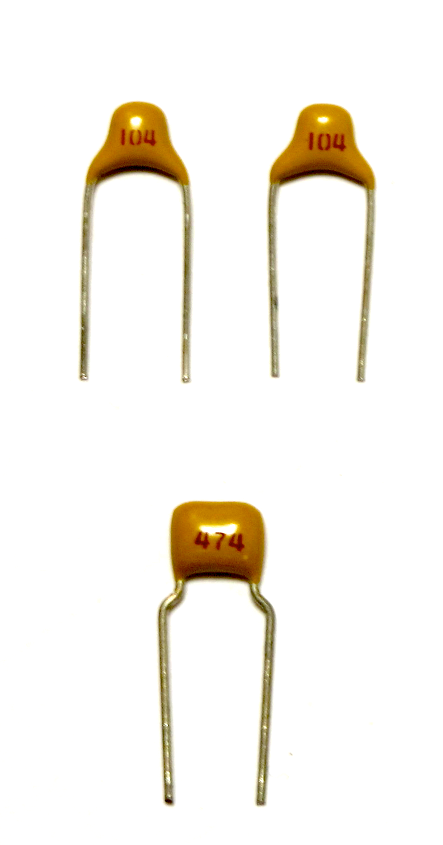
Monolithic capacitors, or mono caps (Figure 11),
are used for capacitors with smaller capacitance.
Mono caps are nonpolar.
Its capacitance can be read from the markings on the capacitor.
Usually, there are three numbers,
and the capcaitance
is the first two numbers, added with as many 0s as specified in the third number
(i.e., multiply by 10 raised to the power of the third number), in pF.
For example,
a capacitor marked "274" has a capacitance of
27 x 104 pF = 270000 pF = 270nF = 0.27µF.
What are the capacitances of the capacitors in
Figure 11?
In a circuit diagram,
nonpolar capacitors are usually marked
without anything in the middle
of the two parallel lines.
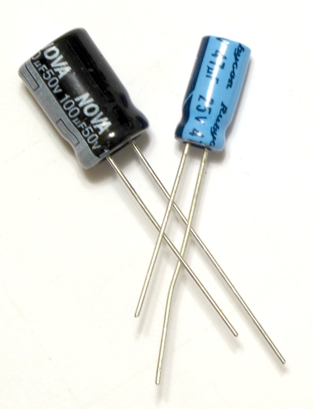
Another kind of capacitors used is called electrolytic capacitor.
They got their names because electrolytes are used in
constructing them.
Electrolytic capacitor are polarized,
that is,
they have positive (+) and a negative (-) connections
which cannot be reversed.
Their capacitance are usually larger,
from a few µF to thousands of µF.
Because of their larger physical size,
their capacitances are usually marked
directly on the component.
The polarity of the leads are also marked,
usually by marking the negative terminal with a band of - signs,
though some of them would mark only the positive terminal or both.
In a circuit diagram,
polarized capacitors such as electrolytic capactiros are usually marked
with slanted lines in the middle
of the two parallel lines.
The polarity are also marked,
typically by marking the + terminal,
though sometimes both + and - terminals are marked.
Also, the lead for the + terminal of a new capacitor are usually longer
than that for the - terminal.
Yet, the marking on the component should be treated as definitive.
Now the only unexplained component in the circuit diagram
has the symbol of a big triangle pointing to a thick line,
with two small arrows near it.
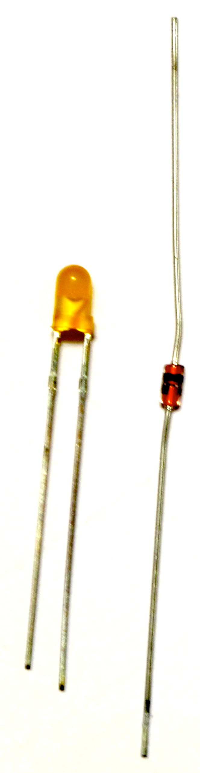
It is the light emitting diode, or LED.
Like ICs, LEDs are semiconductor components.
LED is a special kind of diode,
which is a component that allows one-way flow of current only.
What makes LED different from a normal diode is that
when there is current flow, it lights up.
Thus, they are ideal in being indicators voltage levels.
Usually,
a resistor is needed to limit the current flow through an LED
so it would not be burnt.
Since an LED allows unidirectional current flow only,
it is polarized.
The direction of current flow is along the triangle in the circuit diagram.
The side current enters is marked as positive (+),
and the other side negative (-).
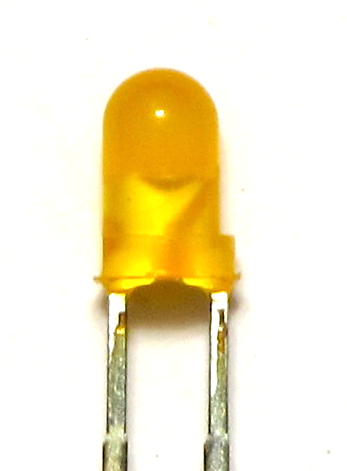
Similar to capacitors,
the lead on the positive side of a new LED is often longer.
You can also determine the polarity by
looking at the transparent or translucent LED itself
(Figure 13).
Inside an LED, one side is larger in size than the other.
The larger side connects to the negative (-) terminal.
For other types of diodes including the Zener diode
(Figure 14),
the negative terminal is marked by a bar on the component package.
Figure 13. Light emitting diode (LED) 圖十三.發光二極管Figure 14. Diodes: LED and Zener Diode 圖十四.二極管:發光二極管和然納二極管
Now that we understand the schematic diagram of the circuit and
can identify the components,
it's time to construct the monostable circuit.
現在明白了如何閱讀電路圖和辨認電子元件,是時間製造單穩態電路了。
Constructing the monostable circuit 製作單穩態電路
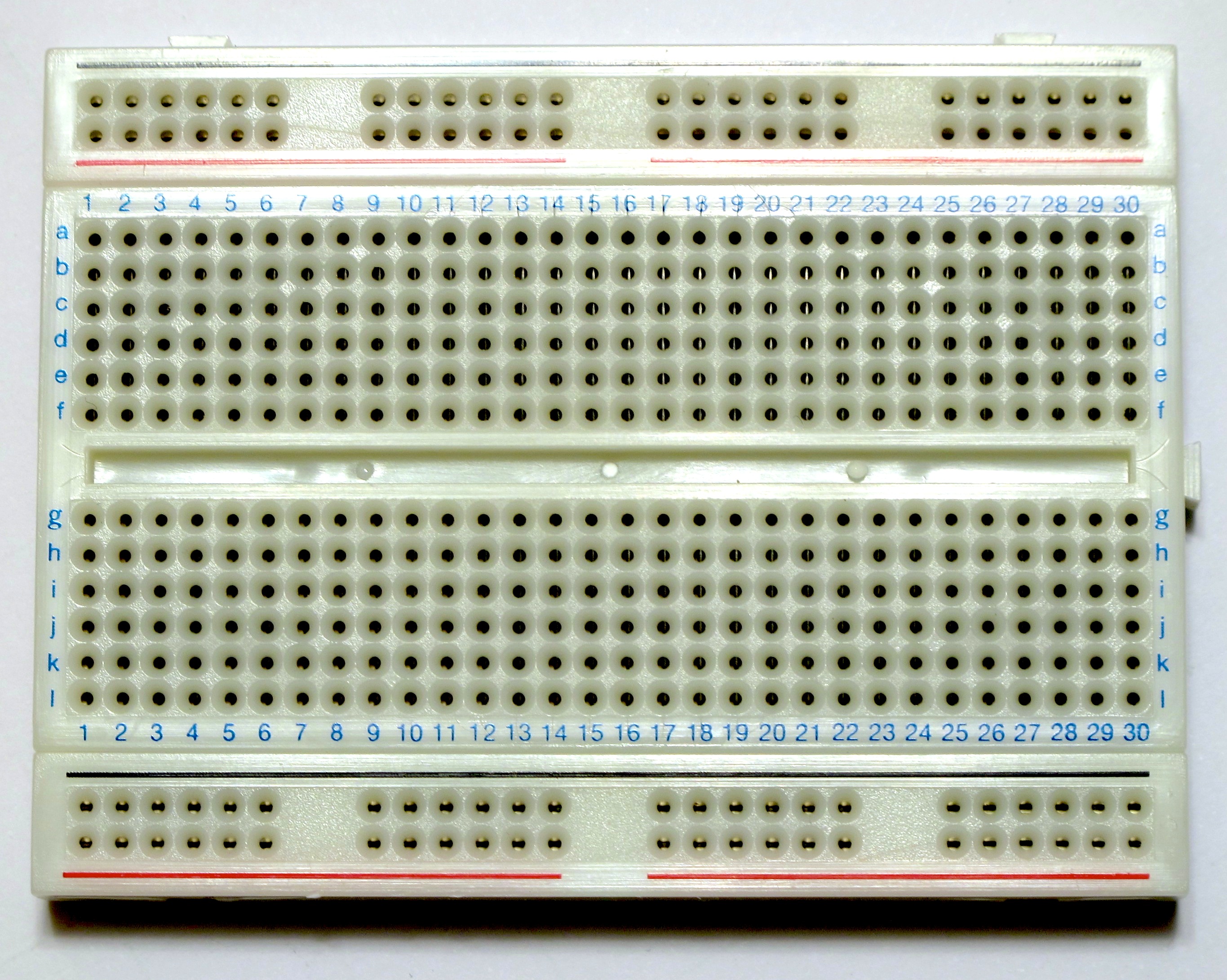
One easy way of constructing a circuit temporarily for experiment is to use a breadboard.
A breadboard is a board with internal connections
and holes for placing components.
Usually,
there are connected holes on the two sides for power supply connections
(black for ground, red for positive voltage),
and those in the middle are connected every row,
though rows and rows are not connected.
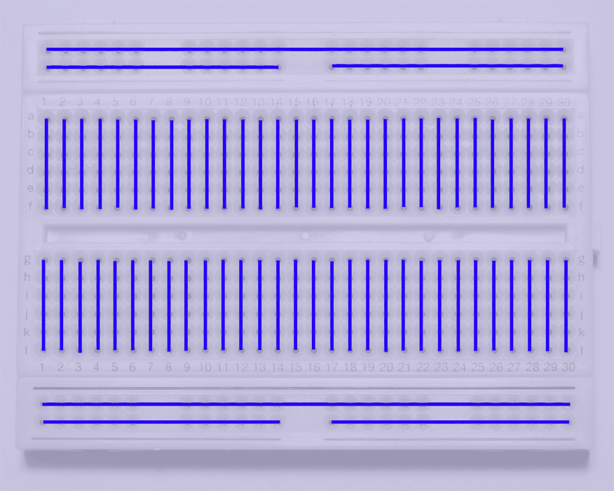
Figure 15 shows the breadboard used in the workshop and
Figure 16 shows
its internal connections.
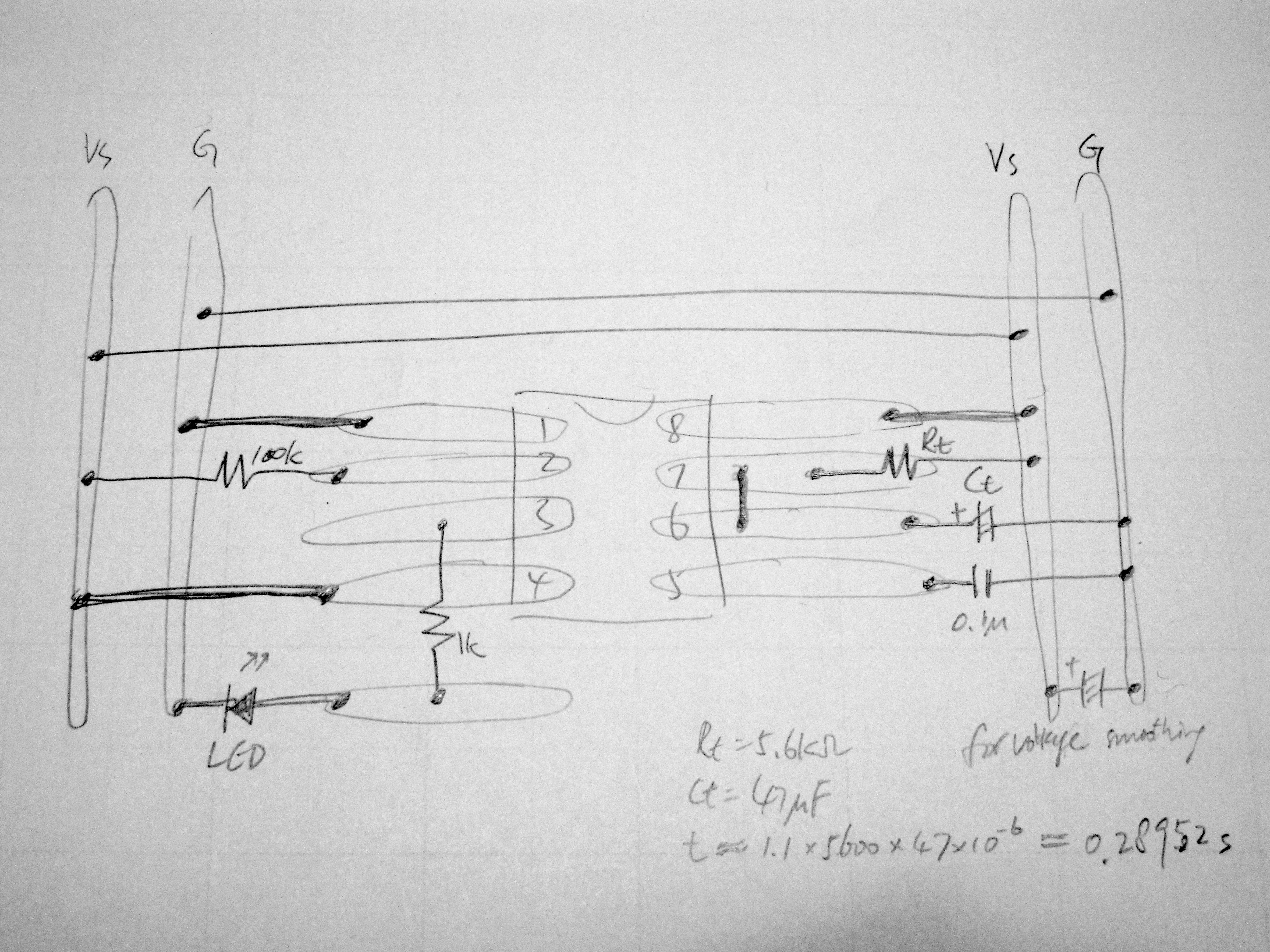
To use the breadboard to construct the circuit,
some planning is needed to make sure the circuit connections are
equivalent to that shown in the circuit schematic.
Figure 17 shows our plan.
Jumper wires are used to connect
some of the middle bars to the power supply bars as required in the circuit schematic,
and the two power supply bars on the two sides have to be connected as well.
Note that an extra capacitor is added to the lower right hand side of our plan
which is used to smooth the voltage supplied to the IC when it changes state.
The value of this capacitor does not matter much as long as it is reasonably large;
47µF or 100µF should be good enough.
The choice of values for Rt and Ct
and the calculation of the time constant are also shown in the plan.
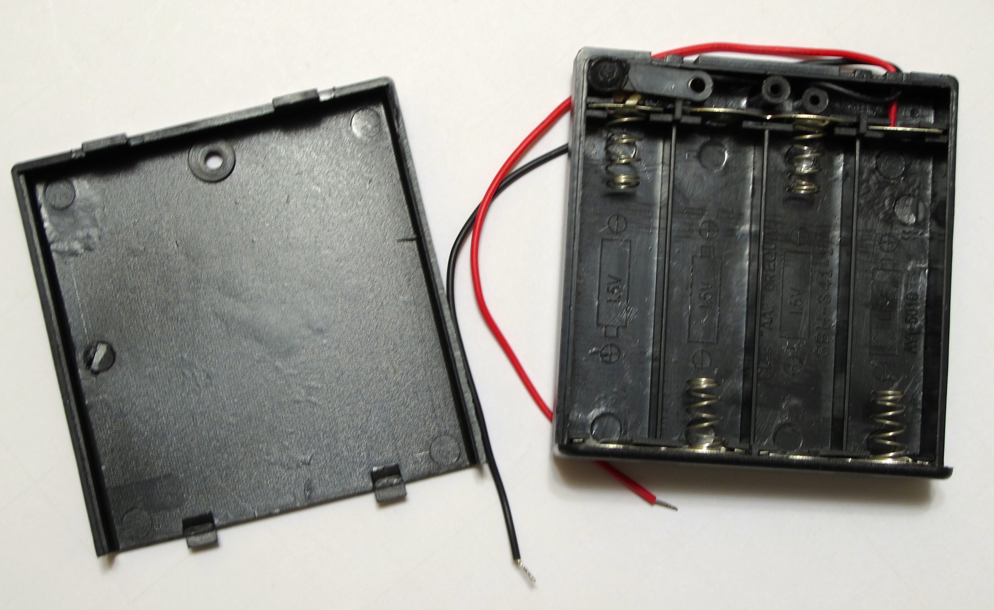
The power is supplied by the battery case with a power switch,
shown in Figure 18.
The red wire correspond to the positive power supply,
and the black wire the ground.
With four AA batteries,
the supply voltage would be 4 x 1.5V = 6V.
Before connecting the battery case and testing the circuit,
check very carefully that
the connections on the breadboard,
the orientation of the IC,
and polarity of the LED and capacitors are correct.
After checking,
switch off the power on the battery case,
and connect it to the circuit.
Make sure the polarity of the power supply connections are correct.
Wrong connections may burn out the IC or cause fire if the battery is short circuited.
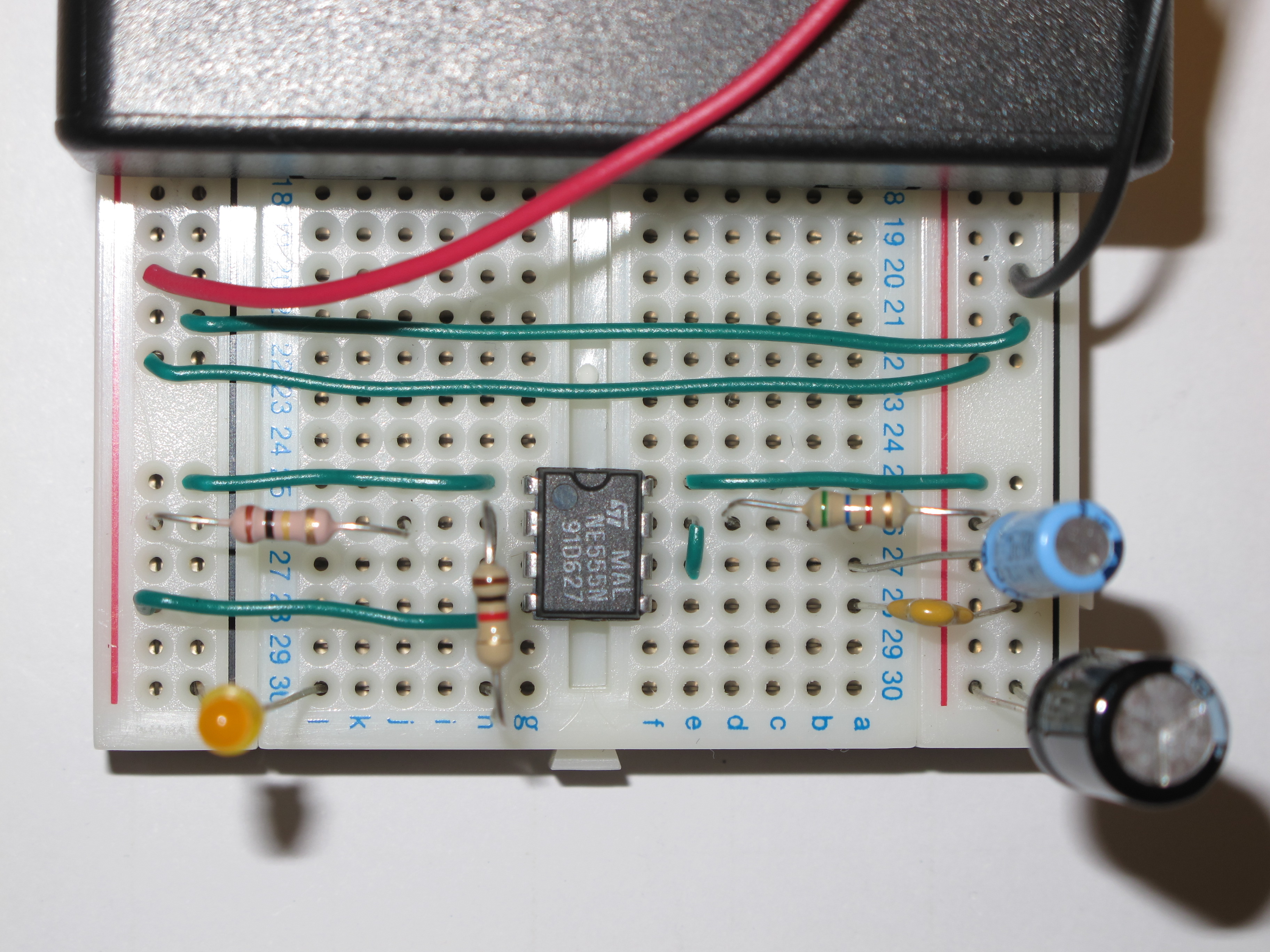
Since the circuit is small,
if you follow the breadboard plan,
the monostable circuit takes up only a few rows of space on the breadboard,
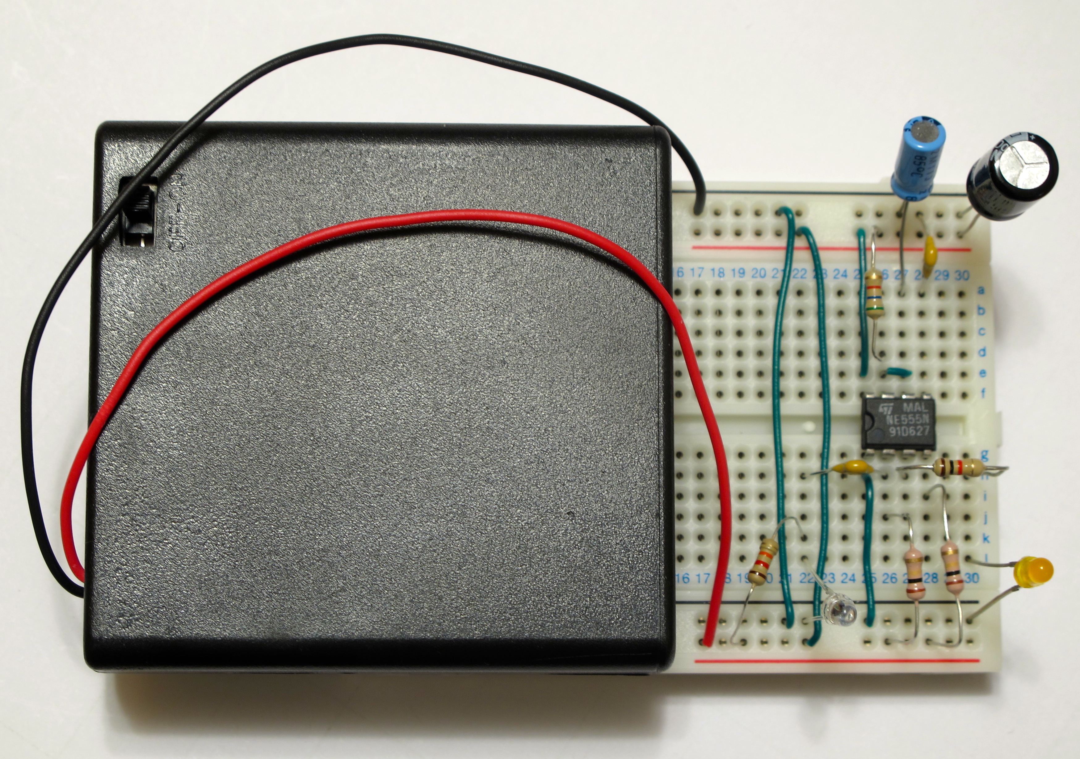
as shown in Figure 19.
Figure 15. Breadboard 圖十五.麵包版Figure 16. Internal connections of the breadboard 圖十六.麵包版的內部連線Figure 17. Plan for placing components on a breadboard 圖十七.麵包版上安放零件的草圖Figure 18. Battery case 圖十八.電池盒Figure 19. Monostable circuit on breadboard 圖十九.麵包版上的單穩態電路
Testing the monostable circuit 測試單穩態電路
Since a low voltage pulse to the Trigger pin (pin 2) of NE555 monostable circuit
would cause it to spring into action,
and that its pin 1 is the ground pin,
the easiest way to test is to temporarily short circuit
pins 1 and 2 of the NE555 using a wire or something metal.
Of course, remember to turn on the power before testing.
After triggering,
the LED should stay on for about 0.3 second,
then go off.
If the test fails,
turn off the power and check the connection and polarity of components one by one.
In this workshop,
we use inductor detector to trigger the monostable circuit.
The simplest inductor detector is just a coil in series with a coupling capacitor,
shown earlier in
Figure 4.
Because a capacitor is used to block DC signals,
the output of the inductor detector can be directly used as the trigger input of the monostable circuit.
Theoretically,
we can calculate the best capacitance and inductance for optimal detection of electric arc discharges.
Yet, because the calculation can be quite complicated,
let us experiment a bit.
Since capacitance values cannot be changed easily,
let us fix it so that C = 0.1µF.
On our breadboard,
one of the leads of the 0.1µF capacitor should be connected to pin 2 of the NE555 IC,
and another lead should be seated on one of the holes whose connection bar does not connect to anything else.
Now let us construct the inductor by making a coil.
Wind about 6 to 8 turns of a piece of wire on a water bottle,
take the bottle out afterwards,
and this is our inductor.
When winding,
make sure that the ends of the coil are long enough
for connecting to the breadboard.
Connecting one end of the coil to the capacitor,
and the other end to the ground bar,
and the circuit is complete.
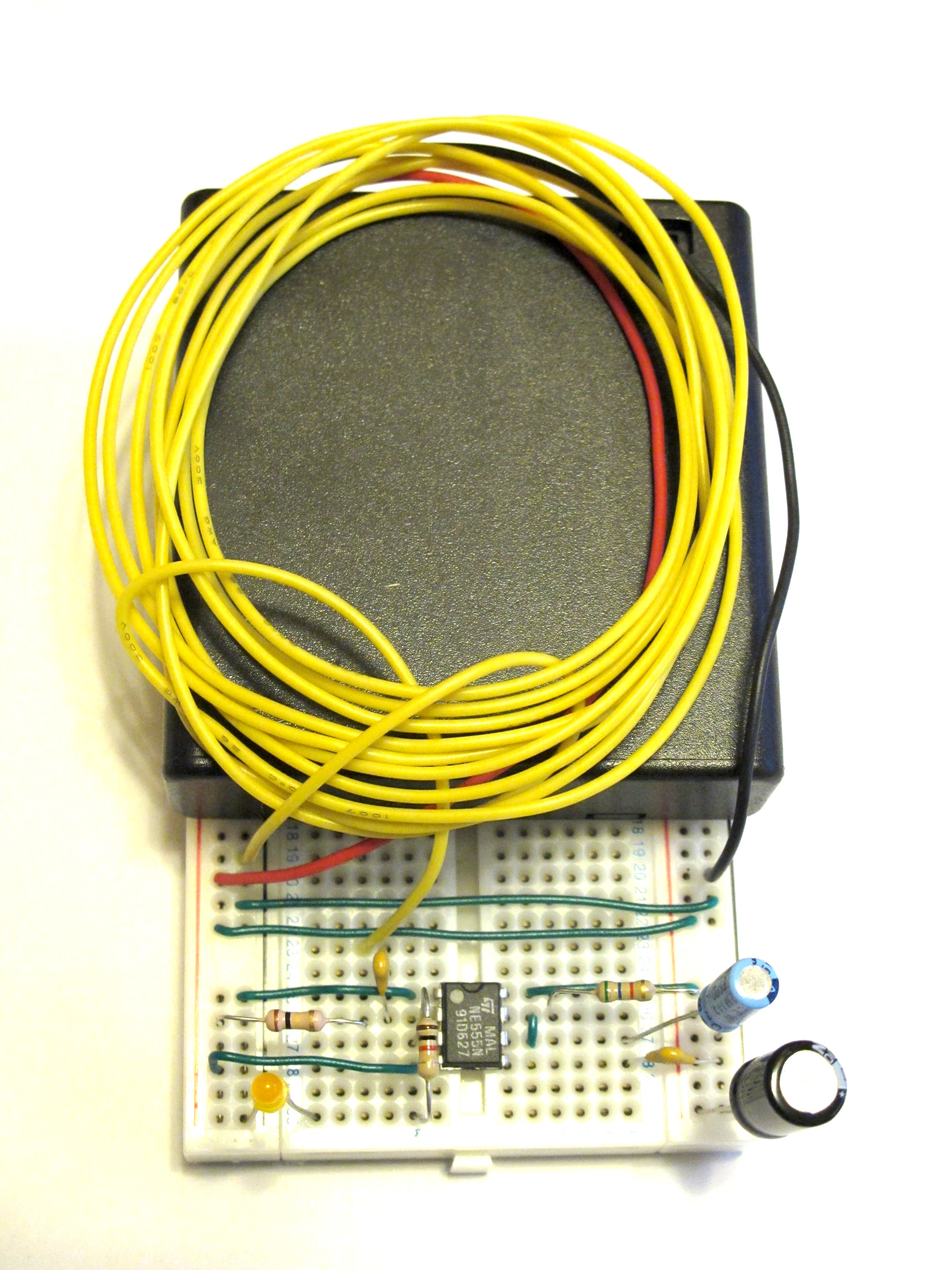
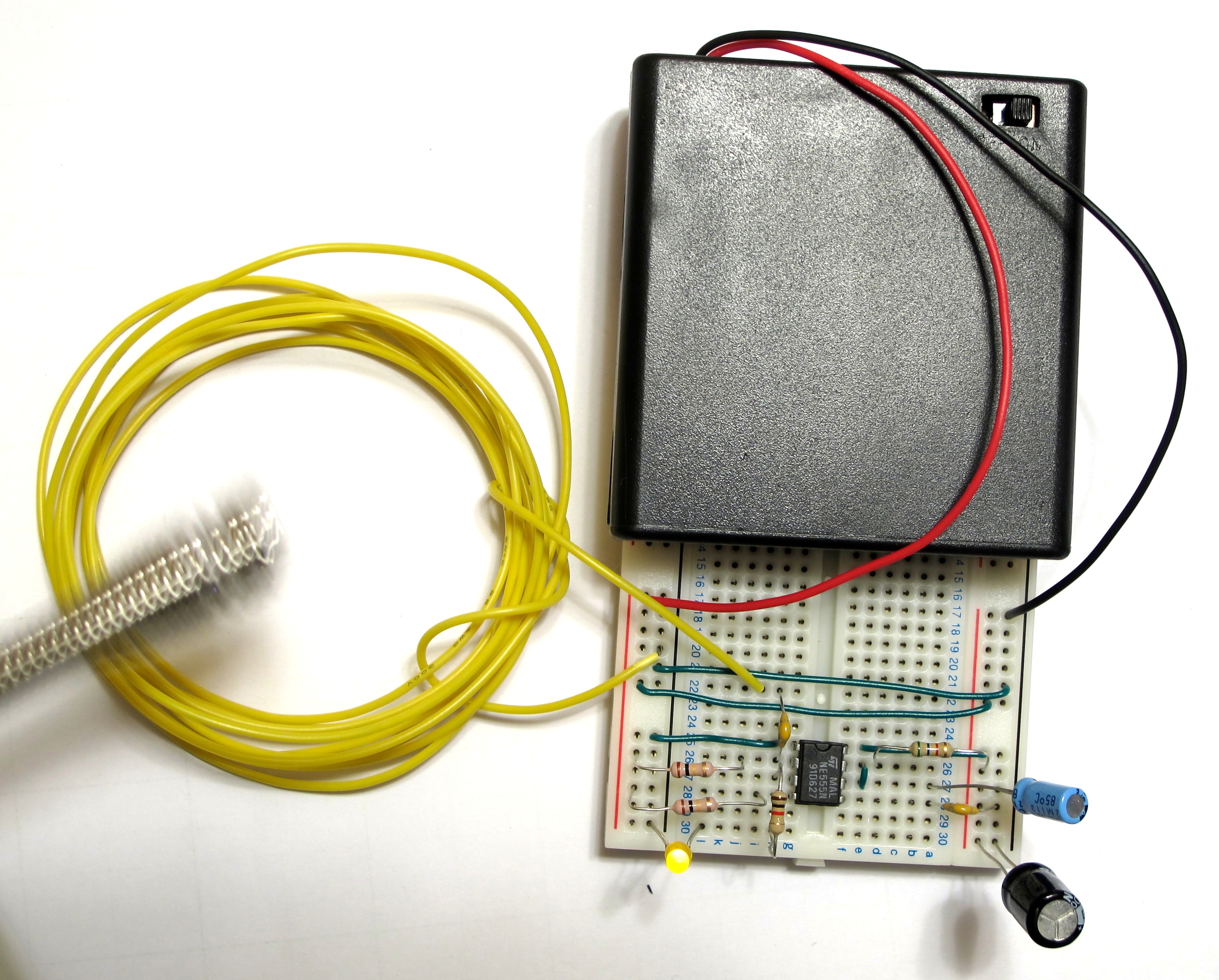
The finished circuit would look like the one in
Figure 20.
It's time to test the circuit using a electric arc lighter!
Switch on the circuit,
and generate electric arc using the electric arc lighter near the coil,
and the LED should light up for a while.
Figure 21
shows the circuit being tested and the LED lighting up.
(The circuit in the photo is slightly different from the one introduced but the difference is inconsequential)
Figure 20. Inductor detector coupled with monostable circuit 圖二十.電感器感應電磁波耦合單穩態電路Figure 21. Inductor detector with monostable circuit being tested 圖二十一.電感器感應電磁波耦合單穩態電路測試中
Time to experiment! 實驗時間!
Since the inductor is just a coil that can be wound and unwound easily,
it would be interesting to experiment
to see the effect of construction of the coil on the sensitivity of the detector circuit.
Here are some ways for the interested to explore:
Is the electric arc detection directional?
How does sensitivity change with the number of turns of the coil?
How does sensitivity change with the size of the coil?
Would an 8-shaped coil be more sensitive or less?
Does the sensitivity change if we put some magnetic materials (e.g., iron) inside the coil?
Electric arc discharge induces current that flow in both directions in the inductor.
When coupled to the monostable,
the large induced current may cause a high voltage that would damage the IC.
Hence, practically,
we should protect the input of the monostable from seeing high voltages.
One way is to put a
Zener diode with a voltage rating similar to the supply voltage
from the ground to the input pin of the iC.
The disadvantage is that this would desensitizes the detector.
Though with the disadvantage,
protection circuit should be in place for out-of-lab use.
While the LC resonator circuit may need components to amplify the signal for coupling to the monostable circuit,
similar to the inductor-based electromagnetic disturbance detector,
the light intensity change detector introduced in
Figure 6 can be coupled directly to the monostable circuit.
Figure 22 shows the coupled circuit.