MOA • #20 • 17-3-1998
St (r1), r2
1. MAR <- [R1]
2. Read
3. Wait for the MFC signal
4. R2 <- [MDR]
The main memory is of some distance away from the CPU, and it takes time to fetch a word from it. The CPU cannot carry on until the fetching completes. The MFC ("memory function completed") signal provides the necessary "handshake".
Using a signal to notify a party which is waiting for the signal is the asynchronous mode of interaction/handshake between two parties (the CPU and the main memory in this case).
The other mode is the synchronous mode where two or more parties observe the pulses generated from a clock, and act according to these pulses.
Analogy: "Copy my file at 3 pm today (it should be ready by then)." (synchronous) "Please wait for my email, and then you may copy my file." (asynchronous)
Both modes are common in CPU design.
To store a word in memory, the CPU performs the following actions. (R1 contains the address; R2 the data.)
1. MAR <- [R1]
2. MDR <- [R2]
3. Write
4. Wait for MFC
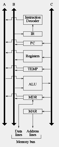
Here, it might be possible for the CPU to perform Steps 1 and 2 simultaneously. Unfortunately, with the organization as shown below, such possibility cannot be realized. The reason is that there is only one internal CPU bus and the two transfers would clash.

The above is a single-bus organization. The following is a multi-bus organization (with three buses). With more buses, it is possible to perform Steps 1 and 2 above simultaneously.


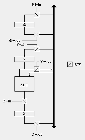
A gate is like a traffic light. When it is turned on or enabled (i.e., green), data would flow along the path concerned in the prescribed direction.
At any time, only one piece of data should be allowed to flow across the internal CPU bus.
Every component inside the CPU has both an input path and an output path. In most cases they are "guarded" by an input gate and an output gate, respectively.
To implement the transfer of data from one component to another. We need to turn on at least two gates, the output gate of the former, and the input gate of the latter.
The following adds two numbers by opening and closing the appropriate gates at the appropriate times.
1. R1out, Yin
2. R2out, Add, Zin
3. Zout, R3in
step     actions
1.   PC-out, MAR-in, Read, Clear Y, Set carry-in to ALU, Add, Z-in
2.   Z-out, PC-in, WMFC
3.   MDR-out, IR-in
4.   R3-out, MAR-in, Read
5.   R1-out, Y-in, WMFC
6.   MDR-out, Add, Z-in
7.   Z-out, R1-in, End
And the following to implement an unconditional branch instruction.
step     actions
1.   PC-out, MAR-in, Read, Clear Y, Set carry-in to ALU, Add, Z-in
2.   Z-out, PC-in, WMFC
3.   MDR-out, IR-in
4.   PC-out, Y-in
5.   Offset-field-of-IR-out, Add, Z-in
6.   Z-out, PC-in, End
In the Add example, the "Set carry-in to ALU" is to set the carry-in line of the ALU to 1.
Note that for brevity, we have not tried to further separate some the actions (that appear in the same line, separated by commas). For example, a Read should not be issued until the MAR has been loaded the new address, the Add cannot be performed until the carry-in line is set, etc. That is, within a step, some actions can be carried out simultaneously while some must be one after another.
There are two kinds of control unit: hardwired and microprogrammed.
The chef example as a analogy: a hardwired chef remembers all the recipes, and when given an order to cook, he/she would quickly get on with the task; a microprogrammed chef remembers only the basic techniques of cooking, and to cook a dish, he/she has to look at/follow the recipe.
The advantage of hardwired control is that it is direct and fast. Its disadvantage is the lack of flexibility. A chef may still learn and remember new recipes, but a hardwired control is cast in iron and cannot be changed; neither can new instructions be added.
On the other hand, a microprogrammed control allows changes, adding of instructions, etc.
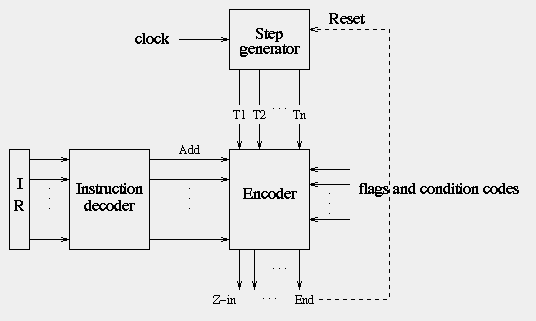
The following shows a simplified structure of a control unit based on the hardwired approach.

The Instruction decoder, based on the input (contents of IR), sets one of its output lines to high (true), indicating to the Encoder what instruction, e.g., Add, is being executed
The Encoder takes the various inputs and generates the necessary
control signals at different time steps. The output lines
at the bottom of the picture are those signals; one of them, for
example, is Z-in which is implemented by the Encoder as
The Z-in signal will be issued at step 1 for all instructions, at step 6 of the Add instruction, at step 5 of the Br(anch) instruction, and so on.
Alternatively, the control remembers none of these, but would consult something called the control store (analogy: the recipe book) to determine the steps to take for executing the instruction on hand.
Inside the control store are a bunch of tiny "programs", each corresponding to a machine instruction. For the Add instruction above, for example, the program is as shown below. Try to compare it with what we showed previously.
              microinstructions
      a b c d e f g h i j k l m n o p q
step
1.    0 1 1 1 0 0 0 1 1 1 1 0 0 0 0 0 0
2.    1 0 0 0 0 0 0 0 0 0 0 1 0 0 0 1 0
3.    0 0 0 0 1 1 0 0 0 0 0 0 0 0 0 0 0
4.    0 0 1 1 0 0 0 0 0 0 0 0 0 0 1 0 0
5.    0 0 0 0 0 0 1 0 0 0 0 0 1 0 0 1 0
6.    0 0 0 0 1 0 0 0 0 1 1 0 0 0 0 0 0
7.    0 0 0 0 0 0 0 0 0 0 0 1 0 1 0 0 1
where
a = PC-in
b = PC-out
c = MAR-in
d = Read
e = MDR-out
f = IR-in
g = Y-in
h = Clear Y
i = Carry-in
j = Add
k = Z-in
l = Z-out
m = R1-out
n = R1-in
o = R3-out
p = WMFC
q = End
The program is officially called a microroutine (for the instruction Add (R3),R1). The entire collection of microroutines for all the CPU's instructions constitute the microprogram for the CPU.
Each line, called a microinstruction, of the microroutine corresponds to one step in the hardwired control solution.
All of the microinstructions involve activating various signals (PC-in, PC-out, etc.). Such an instruction is therefore also called a control word.
There are other instructions (not shown in the above example) which do not activate any signals. An example is a branch (to some location inside the microprogram) instruction.
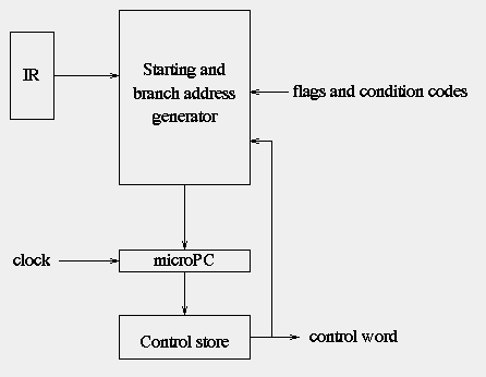
How are microinstructions executed (by a microprogrammed control unit)? The organization of a microprogrammed control unit is as shown below.

address   microinstruction
  0       PC-out, MAR-in, Read, Clear Y, Set carry-in to ALU, Add, Z-in
  1       Z-out, PC-in, WMFC
  2       MDR-out, IR-in
  3       Branch to starting address of appropriate microroutine
  ....    ....
 25       PC-out, Y-in, if N = 0 branch to microinstruction 0
 26       Offset-field-of-IR-out, Add, Z-in
 27       Z-out, PC-in, End
Note that the above fragments of a microprogram could have been expressed as just a series of control words consisting of 1s and 0s. It is presented the way it is so that we don't have to do the mental translation from bits to signals ourselves.
The operations of the microprogrammed control unit are analogous to the operations of the CPU:
So one system has (or translates into) many programs, one program has many CPU instructions, one CPU instruction has many microinstructions, and one microinstruction has many signals.
In fact, some of the signals are "mutually exclusive" -- i.e., when one of them is on, the others must be off. For example, the signals that select the function of the ALU are mutually exclusive. You cannot request Add and Mul at the same time.
Based on the above, we can "encode" the signals so that the control word becomes narrow. For example, we could use two bits to encode Add, Sub, Mul, Div, which would otherwise take four bits.
Highly encoded schemes that use compact codes to specify only a small number of control functions (out of many possible ones) in each microinstruction are referred to as a vertical organization.
With vertical organization, the control store becomes smaller, an advantage for the hardware designer.